RRVV2VVQ4-6533D-R9
24-port sector/multibeam antenna, 4x 694–960, 4x 1695-2690MHz 65° HPBW, 8x 1710-2690MHz 4x33° HPBW and 8x 2300-3800MHz, 90° HPBW 9x RET
Features and Benefits
- Enhances network capacity through six sectors on high band while maintaining low band coverage layer through three sectors with only three antenna faces
- Includes 1x 4-Column Array for 2300-3800MHz and calibration port. Column spacing optimized to support Soft Split Beamforming
Specifications
General Specifications
| Antenna Type | Sector- and beamforming |
| Band | Multiband |
| Calibration Connector Interface | M-LOC |
| Calibration Connector Quantity | 1 |
| Color | Light Gray (RAL 7035) |
| Grounding Type | RF connector inner conductor and body grounded to reflector and mounting bracket |
| Performance Note | Outdoor usage |
| Radome Material | Fiberglass, UV resistant |
| Reflector Material | Aluminum |
| RF Connector Interface | 4.3-10 Female | M-LOC |
| RF Connector Location | Bottom |
| RF Connector Quantity, high band | 8 |
| RF Connector Quantity, mid band | 12 |
| RF Connector Quantity, low band | 4 |
| RF Connector Quantity, total | 24 |
Remote Electrical Tilt (RET) Information
| RET Hardware | CommRET v2 |
| RET Interface | 8-pin DIN Female | 8-pin DIN Male |
| RET Interface, quantity | 2 female | 2 male |
| Input Voltage | 10–30 Vdc |
| Internal RET | High band (1) | Low band (2) | Mid band (6) |
| Power Consumption, active state, maximum | 8 W |
| Power Consumption, idle state, maximum | 1 W |
| Protocol | 3GPP/AISG 2.0 |
Dimensions
| Width | 579 mm | 22.795 in |
| Depth | 212 mm | 8.346 in |
| Length | 2688 mm | 105.827 in |
| Net Weight, antenna only | 67 kg | 147.710 lb |
Array Layout
| Click on image to enlarge. |

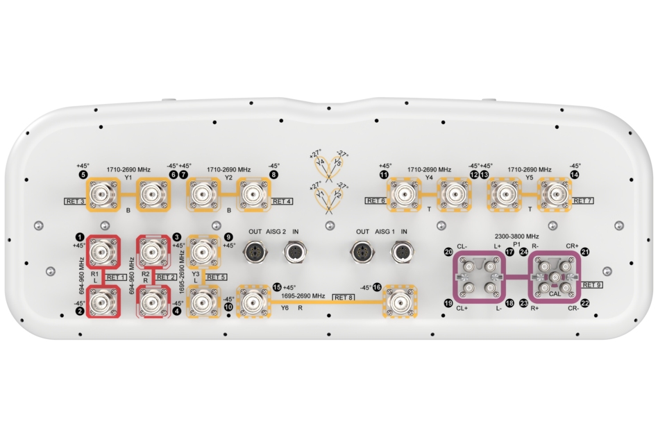
Port Configuration
| Click on image to enlarge. |

Electrical Specifications
| Impedance | 50 ohm |
| Operating Frequency Band | 694 – 960 MHz | 1695 – 2690 MHz | 1710 – 2690 MHz | 2300 – 3800 MHz |
| Polarization | ±45° |
Electrical Specifications
| R1,R2 | R1,R2 | R1,R2 | Y1,Y2,Y4,Y5 | Y1,Y2,Y4,Y5 | Y1,Y2,Y4,Y5 | Y3,Y6 | Y3,Y6 | Y3,Y6 | P1 | P1 | |
| Frequency Band, MHz | 694–790 | 790–890 | 890–960 | 1710–1920 | 1920–2180 | 2300–2690 | 1695–1920 | 1920–2180 | 2300–2690 | 2300–2690 | 3300–3800 |
| RF Port | 1-4 | 1-4 | 1-4 | 5-8,11-14 | 5-8,11-14 | 5-8,11-14 | 9,10,15,16 | 9,10,15,16 | 9,10,15,16 | 17-24 | 17-24 |
| Gain, dBi | 16.2 | 16.7 | 16.8 | 18.7 | 19.8 | 20.5 | 16.2 | 17.4 | 17.8 | 15.8 | 16.6 |
| Gain at Mid Tilt, dBi | 15.9 | 16.5 | 16.6 | 18.1 | 19.6 | 20.3 | 15.8 | 17.1 | 17.6 | 14.9 | 15.8 |
| Beam Centers, Horizontal, degrees | ±27 | ±27 | ±27 | ||||||||
| Beamwidth, Horizontal, degrees | 70 | 61 | 60 | 35 | 32 | 27 | 67 | 61 | 58 | 90 | 66 |
| Beamwidth, Vertical, degrees | 8.9 | 8 | 7.4 | 7.3 | 6.5 | 5.4 | 7.1 | 6.5 | 5.4 | 6 | 5.5 |
| Beam Tilt, degrees | 2–12 | 2–12 | 2–12 | 2–12 | 2–12 | 2–12 | 2–12 | 2–12 | 2–12 | 2–12 | 2–12 |
| USLS (First Lobe), dB | 16 | 20 | 19 | 17 | 18 | 20 | 15 | 16 | 17 | 11 | 14 |
| Front-to-Back Ratio at 180°, dB | 32 | 31 | 30 | 33 | 35 | 34 | 33 | 34 | 32 | 28 | 27 |
| Coupling level, Amp, Antenna port to Cal port, dB | 26 | 26 | |||||||||
| Coupling level, max Amp Δ, Antenna port to Cal port, dB | ±2 | ±2 | |||||||||
| Coupler, max Amp Δ, Antenna port to Cal port, dB | 0.9 | 0.9 | |||||||||
| Coupler, max Phase Δ, Antenna port to Cal port, degrees | 7 | 7 | |||||||||
| Isolation, Cross Polarization, dB | 25 | 25 | 25 | 25 | 25 | 25 | 25 | 25 | 25 | 23 | 23 |
| Isolation, Inter-band, dB | 25 | 25 | 25 | 25 | 25 | 25 | 25 | 25 | 25 | 25 | 25 |
| Isolation, Co-polarization, dB | 18 | 18 | |||||||||
| Isolation, Beam to Beam, dB | 17 | 17 | 17 | ||||||||
| VSWR | Return loss, dB | 1.5 | 14.0 | 1.5 | 14.0 | 1.5 | 14.0 | 1.5 | 14.0 | 1.5 | 14.0 | 1.5 | 14.0 | 1.5 | 14.0 | 1.5 | 14.0 | 1.5 | 14.0 | 1.5 | 14.0 | 1.5 | 14.0 |
| PIM, 3rd Order, 2 x 20 W, dBc | -150 | -150 | -150 | -150 | -150 | -150 | -150 | -150 | -150 | -143 | -143 |
| Input Power per Port at 50°C, maximum, watts | 300 | 300 | 300 | 250 | 250 | 200 | 250 | 250 | 200 | 75 | 75 |
Electrical Specifications, BASTA
| Frequency Band, MHz | 694–790 | 790–890 | 890–960 | 1710–1920 | 1920–2180 | 2300–2690 | 1695–1920 | 1920–2180 | 2300–2690 | 2300–2690 | 3300–3800 |
| Gain by all Beam Tilts, average, dBi | 15.8 | 16.4 | 16.5 | 17.9 | 19.3 | 19.9 | 15.7 | 16.8 | 17.3 | 14.9 | 15.7 |
| Beamwidth, Horizontal Tolerance, degrees | ±6 | ±4 | ±4 | ±4 | ±3 | ±3 | ±9 | ±5 | ±6 | ±20 | ±12 |
| Beamwidth, Vertical Tolerance, degrees | ±0.5 | ±0.5 | ±0.3 | ±0.5 | ±0.4 | ±0.4 | ±0.5 | ±0.5 | ±0.4 | ±0.6 | ±0.4 |
| USLS, beampeak to 20° above beampeak, dB | 16 | 16 | 17 | 15 | 17 | 14 | 14 | 15 | 12 | 11 | 12 |
| Front-to-Back Total Power at 180° ± 30°, dB | 25 | 25 | 24 | 28 | 29 | 28 | 25 | 29 | 27 | 22 | 22 |
| CPR at Boresight, dB | 21 | 22 | 22 | 16 | 21 | 21 | 18 | 23 | 20 | 14 | 16 |
| CPR at Sector, dB | 13 | 10 | 13 | 8 | 8 | 5 | 8 | 3 | |||
| CPR at 10 dB Horizontal Beamwidth, dB | 8 | 12 | 13 |
Electrical Specifications, Broadcast 65
| Frequency Band, MHz | 694–790 | 790–890 | 890–960 | 1710–1920 | 1920–2180 | 2300–2690 | 1695–1920 | 1920–2180 | 2300–2690 | 2300–2690 | 3300–3800 |
| Gain, dBi | 17.6 | 16.9 | |||||||||
| Beamwidth, Horizontal at 3 dB, degrees | 65 | 65 | |||||||||
| Beamwidth, Vertical, degrees | 5.9 | 5.6 | |||||||||
| Front-to-Back Total Power at 180° ± 30°, dB | 25 | 23 | |||||||||
| USLS (First Lobe), dB | 12 | 14 |
Electrical Specifications, Service Beam
| Frequency Band, MHz | 694–790 | 790–890 | 890–960 | 1710–1920 | 1920–2180 | 2300–2690 | 1695–1920 | 1920–2180 | 2300–2690 | 2300–2690 | 3300–3800 |
| Steered 0° Gain, dBi | 20.4 | 21.2 | |||||||||
| Steered 0° Beamwidth, Horizontal, degrees | 26 | 18 | |||||||||
| Steered 0° Front-to-Back Total Power at 180° ± 30°, dB | 30 | 27 | |||||||||
| Steered 0° Horizontal Sidelobe, dB | 12 | 11 | |||||||||
| Steered 30° Gain, dBi | 19.6 | 19.4 | |||||||||
| Steered 30° Beamwidth, Horizontal, degrees | 27 | 21 | |||||||||
| Steered 30° Front-to-Back Total Power at 180° ± 30°, dB | 28 | 27 |
Electrical Specifications, Soft Split
| Frequency Band, MHz | 694–790 | 790–890 | 890–960 | 1710–1920 | 1920–2180 | 2300–2690 | 1695–1920 | 1920–2180 | 2300–2690 | 2300–2690 | 3300–3800 |
| Gain, dBi | 19.3 | ||||||||||
| Beamwidth, Horizontal, degrees | 31 | ||||||||||
| Front-to-Back Total Power at 180° ± 30°, dB | 28 | ||||||||||
| Horizontal Sidelobe, dB | 15 |
Mechanical Specifications
| Wind Loading @ Velocity, frontal | 764.0 N @ 150 km/h (171.8 lbf @ 150 km/h) |
| Wind Loading @ Velocity, lateral | 328.0 N @ 150 km/h (73.7 lbf @ 150 km/h) |
| Wind Loading @ Velocity, maximum | 1,220.0 N @ 150 km/h (274.3 lbf @ 150 km/h) |
| Wind Loading @ Velocity, rear | 774.0 N @ 150 km/h (174.0 lbf @ 150 km/h) |
| Wind Speed, maximum | 241 km/h (150 mph) |
Packaging and Weights
| Width, packed | 681 mm | 26.811 in |
| Depth, packed | 368 mm | 14.488 in |
| Length, packed | 2827 mm | 111.299 in |
| Weight, gross | 85.5 kg | 188.495 lb |
Regulatory Compliance/Certifications
| Agency | Classification |
| ISO 9001:2015 | Designed, manufactured and/or distributed under this quality management system |
General Specifications
| Antenna Type | Sector- and beamforming |
| Band | Multiband |
| Calibration Connector Interface | M-LOC |
| Calibration Connector Quantity | 1 |
| Color | Light Gray (RAL 7035) |
| Grounding Type | RF connector inner conductor and body grounded to reflector and mounting bracket |
| Performance Note | Outdoor usage |
| Radome Material | Fiberglass, UV resistant |
| Reflector Material | Aluminum |
| RF Connector Interface | 4.3-10 Female | M-LOC |
| RF Connector Location | Bottom |
| RF Connector Quantity, high band | 8 |
| RF Connector Quantity, mid band | 12 |
| RF Connector Quantity, low band | 4 |
| RF Connector Quantity, total | 24 |
Remote Electrical Tilt (RET) Information
| RET Hardware | CommRET v2 |
| RET Interface | 8-pin DIN Female | 8-pin DIN Male |
| RET Interface, quantity | 2 female | 2 male |
| Input Voltage | 10–30 Vdc |
| Internal RET | High band (1) | Low band (2) | Mid band (6) |
| Power Consumption, active state, maximum | 8 W |
| Power Consumption, idle state, maximum | 1 W |
| Protocol | 3GPP/AISG 2.0 |
Dimensions
| Width | 579 mm | 22.795 in |
| Depth | 212 mm | 8.346 in |
| Length | 2688 mm | 105.827 in |
| Net Weight, antenna only | 67 kg | 147.710 lb |
Electrical Specifications
| Impedance | 50 ohm |
| Operating Frequency Band | 694 – 960 MHz | 1695 – 2690 MHz | 1710 – 2690 MHz | 2300 – 3800 MHz |
| Polarization | ±45° |
Electrical Specifications
| R1,R2 | R1,R2 | R1,R2 | Y1,Y2,Y4,Y5 | Y1,Y2,Y4,Y5 | Y1,Y2,Y4,Y5 | Y3,Y6 | Y3,Y6 | Y3,Y6 | P1 | P1 | |
| Frequency Band, MHz | 694–790 | 790–890 | 890–960 | 1710–1920 | 1920–2180 | 2300–2690 | 1695–1920 | 1920–2180 | 2300–2690 | 2300–2690 | 3300–3800 |
| RF Port | 1-4 | 1-4 | 1-4 | 5-8,11-14 | 5-8,11-14 | 5-8,11-14 | 9,10,15,16 | 9,10,15,16 | 9,10,15,16 | 17-24 | 17-24 |
| Gain, dBi | 16.2 | 16.7 | 16.8 | 18.7 | 19.8 | 20.5 | 16.2 | 17.4 | 17.8 | 15.8 | 16.6 |
| Gain at Mid Tilt, dBi | 15.9 | 16.5 | 16.6 | 18.1 | 19.6 | 20.3 | 15.8 | 17.1 | 17.6 | 14.9 | 15.8 |
| Beam Centers, Horizontal, degrees | ±27 | ±27 | ±27 | ||||||||
| Beamwidth, Horizontal, degrees | 70 | 61 | 60 | 35 | 32 | 27 | 67 | 61 | 58 | 90 | 66 |
| Beamwidth, Vertical, degrees | 8.9 | 8 | 7.4 | 7.3 | 6.5 | 5.4 | 7.1 | 6.5 | 5.4 | 6 | 5.5 |
| Beam Tilt, degrees | 2–12 | 2–12 | 2–12 | 2–12 | 2–12 | 2–12 | 2–12 | 2–12 | 2–12 | 2–12 | 2–12 |
| USLS (First Lobe), dB | 16 | 20 | 19 | 17 | 18 | 20 | 15 | 16 | 17 | 11 | 14 |
| Front-to-Back Ratio at 180°, dB | 32 | 31 | 30 | 33 | 35 | 34 | 33 | 34 | 32 | 28 | 27 |
| Coupling level, Amp, Antenna port to Cal port, dB | 26 | 26 | |||||||||
| Coupling level, max Amp Δ, Antenna port to Cal port, dB | ±2 | ±2 | |||||||||
| Coupler, max Amp Δ, Antenna port to Cal port, dB | 0.9 | 0.9 | |||||||||
| Coupler, max Phase Δ, Antenna port to Cal port, degrees | 7 | 7 | |||||||||
| Isolation, Cross Polarization, dB | 25 | 25 | 25 | 25 | 25 | 25 | 25 | 25 | 25 | 23 | 23 |
| Isolation, Inter-band, dB | 25 | 25 | 25 | 25 | 25 | 25 | 25 | 25 | 25 | 25 | 25 |
| Isolation, Co-polarization, dB | 18 | 18 | |||||||||
| Isolation, Beam to Beam, dB | 17 | 17 | 17 | ||||||||
| VSWR | Return loss, dB | 1.5 | 14.0 | 1.5 | 14.0 | 1.5 | 14.0 | 1.5 | 14.0 | 1.5 | 14.0 | 1.5 | 14.0 | 1.5 | 14.0 | 1.5 | 14.0 | 1.5 | 14.0 | 1.5 | 14.0 | 1.5 | 14.0 |
| PIM, 3rd Order, 2 x 20 W, dBc | -150 | -150 | -150 | -150 | -150 | -150 | -150 | -150 | -150 | -143 | -143 |
| Input Power per Port at 50°C, maximum, watts | 300 | 300 | 300 | 250 | 250 | 200 | 250 | 250 | 200 | 75 | 75 |
Electrical Specifications, BASTA
| Frequency Band, MHz | 694–790 | 790–890 | 890–960 | 1710–1920 | 1920–2180 | 2300–2690 | 1695–1920 | 1920–2180 | 2300–2690 | 2300–2690 | 3300–3800 |
| Gain by all Beam Tilts, average, dBi | 15.8 | 16.4 | 16.5 | 17.9 | 19.3 | 19.9 | 15.7 | 16.8 | 17.3 | 14.9 | 15.7 |
| Beamwidth, Horizontal Tolerance, degrees | ±6 | ±4 | ±4 | ±4 | ±3 | ±3 | ±9 | ±5 | ±6 | ±20 | ±12 |
| Beamwidth, Vertical Tolerance, degrees | ±0.5 | ±0.5 | ±0.3 | ±0.5 | ±0.4 | ±0.4 | ±0.5 | ±0.5 | ±0.4 | ±0.6 | ±0.4 |
| USLS, beampeak to 20° above beampeak, dB | 16 | 16 | 17 | 15 | 17 | 14 | 14 | 15 | 12 | 11 | 12 |
| Front-to-Back Total Power at 180° ± 30°, dB | 25 | 25 | 24 | 28 | 29 | 28 | 25 | 29 | 27 | 22 | 22 |
| CPR at Boresight, dB | 21 | 22 | 22 | 16 | 21 | 21 | 18 | 23 | 20 | 14 | 16 |
| CPR at Sector, dB | 13 | 10 | 13 | 8 | 8 | 5 | 8 | 3 | |||
| CPR at 10 dB Horizontal Beamwidth, dB | 8 | 12 | 13 |
Electrical Specifications, Broadcast 65
| Frequency Band, MHz | 694–790 | 790–890 | 890–960 | 1710–1920 | 1920–2180 | 2300–2690 | 1695–1920 | 1920–2180 | 2300–2690 | 2300–2690 | 3300–3800 |
| Gain, dBi | 17.6 | 16.9 | |||||||||
| Beamwidth, Horizontal at 3 dB, degrees | 65 | 65 | |||||||||
| Beamwidth, Vertical, degrees | 5.9 | 5.6 | |||||||||
| Front-to-Back Total Power at 180° ± 30°, dB | 25 | 23 | |||||||||
| USLS (First Lobe), dB | 12 | 14 |
Electrical Specifications, Service Beam
| Frequency Band, MHz | 694–790 | 790–890 | 890–960 | 1710–1920 | 1920–2180 | 2300–2690 | 1695–1920 | 1920–2180 | 2300–2690 | 2300–2690 | 3300–3800 |
| Steered 0° Gain, dBi | 20.4 | 21.2 | |||||||||
| Steered 0° Beamwidth, Horizontal, degrees | 26 | 18 | |||||||||
| Steered 0° Front-to-Back Total Power at 180° ± 30°, dB | 30 | 27 | |||||||||
| Steered 0° Horizontal Sidelobe, dB | 12 | 11 | |||||||||
| Steered 30° Gain, dBi | 19.6 | 19.4 | |||||||||
| Steered 30° Beamwidth, Horizontal, degrees | 27 | 21 | |||||||||
| Steered 30° Front-to-Back Total Power at 180° ± 30°, dB | 28 | 27 |
Electrical Specifications, Soft Split
| Frequency Band, MHz | 694–790 | 790–890 | 890–960 | 1710–1920 | 1920–2180 | 2300–2690 | 1695–1920 | 1920–2180 | 2300–2690 | 2300–2690 | 3300–3800 |
| Gain, dBi | 19.3 | ||||||||||
| Beamwidth, Horizontal, degrees | 31 | ||||||||||
| Front-to-Back Total Power at 180° ± 30°, dB | 28 | ||||||||||
| Horizontal Sidelobe, dB | 15 |
Mechanical Specifications
| Wind Loading @ Velocity, frontal | 764.0 N @ 150 km/h (171.8 lbf @ 150 km/h) |
| Wind Loading @ Velocity, lateral | 328.0 N @ 150 km/h (73.7 lbf @ 150 km/h) |
| Wind Loading @ Velocity, maximum | 1,220.0 N @ 150 km/h (274.3 lbf @ 150 km/h) |
| Wind Loading @ Velocity, rear | 774.0 N @ 150 km/h (174.0 lbf @ 150 km/h) |
| Wind Speed, maximum | 241 km/h (150 mph) |
Packaging and Weights
| Width, packed | 681 mm | 26.811 in |
| Depth, packed | 368 mm | 14.488 in |
| Length, packed | 2827 mm | 111.299 in |
| Weight, gross | 85.5 kg | 188.495 lb |
| Click on image to enlarge. |
| Click on image to enlarge. |
Regulatory Compliance/Certifications
| Agency | Classification |
| ISO 9001:2015 | Designed, manufactured and/or distributed under this quality management system |
Documentation & Downloads
Assembly Drawing
Product Information
Product Specification
Warranty
Assembly Drawing
Product Compliance Documentation
Product Information
Product Specification
Warranty
Related Products and Accessories
Included Products
Antennas
-
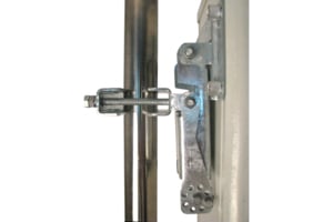
![]() BSAMNT-4 Wide Profile Antenna Downtilt Mounting Kit for 2.4 - 4.5 in (60 - 115 mm) OD round members. Kit contains one scissor top bracket set and one bottom bracket set.
BSAMNT-4 Wide Profile Antenna Downtilt Mounting Kit for 2.4 - 4.5 in (60 - 115 mm) OD round members. Kit contains one scissor top bracket set and one bottom bracket set. -
![]() BSAMNT-M4 Middle Downtilt Mounting Kit for Long Antennas for 2.4 - 4.5 in (60 - 115 mm) OD round members. Kit contains one scissor bracket set.
BSAMNT-M4 Middle Downtilt Mounting Kit for Long Antennas for 2.4 - 4.5 in (60 - 115 mm) OD round members. Kit contains one scissor bracket set.
Structural Support, Tools & Accessories
-
![]() BSAMNT-4 Wide Profile Antenna Downtilt Mounting Kit for 2.4 - 4.5 in (60 - 115 mm) OD round members. Kit contains one scissor top bracket set and one bottom bracket set.
BSAMNT-4 Wide Profile Antenna Downtilt Mounting Kit for 2.4 - 4.5 in (60 - 115 mm) OD round members. Kit contains one scissor top bracket set and one bottom bracket set. -
![]() BSAMNT-M4 Middle Downtilt Mounting Kit for Long Antennas for 2.4 - 4.5 in (60 - 115 mm) OD round members. Kit contains one scissor bracket set.
BSAMNT-M4 Middle Downtilt Mounting Kit for Long Antennas for 2.4 - 4.5 in (60 - 115 mm) OD round members. Kit contains one scissor bracket set.
Included Products
Antennas
-
![]() BSAMNT-4 Wide Profile Antenna Downtilt Mounting Kit for 2.4 - 4.5 in (60 - 115 mm) OD round members. Kit contains one scissor top bracket set and one bottom bracket set.
BSAMNT-4 Wide Profile Antenna Downtilt Mounting Kit for 2.4 - 4.5 in (60 - 115 mm) OD round members. Kit contains one scissor top bracket set and one bottom bracket set. -
![]() BSAMNT-M4 Middle Downtilt Mounting Kit for Long Antennas for 2.4 - 4.5 in (60 - 115 mm) OD round members. Kit contains one scissor bracket set.
BSAMNT-M4 Middle Downtilt Mounting Kit for Long Antennas for 2.4 - 4.5 in (60 - 115 mm) OD round members. Kit contains one scissor bracket set.
Structural Support, Tools & Accessories
-
![]() BSAMNT-4 Wide Profile Antenna Downtilt Mounting Kit for 2.4 - 4.5 in (60 - 115 mm) OD round members. Kit contains one scissor top bracket set and one bottom bracket set.
BSAMNT-4 Wide Profile Antenna Downtilt Mounting Kit for 2.4 - 4.5 in (60 - 115 mm) OD round members. Kit contains one scissor top bracket set and one bottom bracket set. -
![]() BSAMNT-M4 Middle Downtilt Mounting Kit for Long Antennas for 2.4 - 4.5 in (60 - 115 mm) OD round members. Kit contains one scissor bracket set.
BSAMNT-M4 Middle Downtilt Mounting Kit for Long Antennas for 2.4 - 4.5 in (60 - 115 mm) OD round members. Kit contains one scissor bracket set.
-
![]() BSAMNT-4 Wide Profile Antenna Downtilt Mounting Kit for 2.4 - 4.5 in (60 - 115 mm) OD round members. Kit contains one scissor top bracket set and one bottom bracket set.
BSAMNT-4 Wide Profile Antenna Downtilt Mounting Kit for 2.4 - 4.5 in (60 - 115 mm) OD round members. Kit contains one scissor top bracket set and one bottom bracket set. -
![]() BSAMNT-M4 Middle Downtilt Mounting Kit for Long Antennas for 2.4 - 4.5 in (60 - 115 mm) OD round members. Kit contains one scissor bracket set.
BSAMNT-M4 Middle Downtilt Mounting Kit for Long Antennas for 2.4 - 4.5 in (60 - 115 mm) OD round members. Kit contains one scissor bracket set.
Other Ways to Browse
